
About this note
A plain-language summary of the 5 publications listed under this topic on Academic Publications (Topic-wise). Full citations are under References.
Why this matters
Metal foams in electronics coolers, packed beds, sand filters and catalytic converters share one feature: a fluid is pushed through a porous medium, a solid matrix laced with connected pores. Before predicting how much heat such a device moves, one must know how much pressure it takes to drive the flow.
The workhorse model is the Hazen-Dupuit-Darcy (HDD) relation. It says the pressure drop per unit length has two parts: a viscous drag proportional to the flow speed, set by the permeability (a measure of how easily fluid passes through the material), and a form drag proportional to the square of the speed, set by the form coefficient (which captures the extra resistance from flow separating around the solid bits at higher speeds). Everything rests on knowing and reliably, and on knowing where the simple model stops working. Our papers in this area probe exactly those two questions.
What we did
Getting the properties right
The first contribution, with José Lage and Paul Krueger, was a measuring protocol (Lage et al., 2005). The equations defining and were originally definitions of material properties, but are now usually written as momentum balances, and in a real test channel the measured pressure drop also includes friction from the channel walls and other secondary effects. We derived model equations that separate these effects, to guide the design of experiments that isolate and .
With research scholar L. Wilson and S. P. Venkateshan we then tested one assumption hidden in the standard experiment: that the flow enters the porous sample with a flat, uniform (“plug”) velocity profile (Wilson et al., 2006). We ran isothermal water experiments through rod-bundle and fissure-type (blocks with holes drilled through them) porous inserts in a rectangular channel, once with a plug profile at the inlet and once with a fully developed, parabolic-like profile, and compared the and obtained by fitting the HDD model.
Why should the inlet matter? and are meant to be global properties of the porous material: measured once, under isothermal conditions, they should be independent of the fluid and the flow, and reusable with the HDD model to predict the pressure drop in any device built from that material. That holds only if the flow through the test section is plug-like throughout. The form coefficient depends on the shape of the velocity profile across the channel at every point along the sample, so the same material can return a different if the flow arrives with a non-uniform profile. The test section was short (about 3.2 hydraulic diameters long), and the inserts were bundles of 3 mm and 1 mm aluminium rods, a Perspex block with 28 holes of 3 mm diameter, and an aluminium block with 84 holes of 2 mm diameter, with porosities of 0.18 to 0.25.
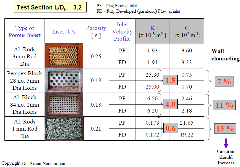
Permeability K and form coefficient C measured for the four inserts with a plug (PF) and a fully developed (FD) inlet profile. The numbers in the grey boxes are the percentage changes between the two: under 4% for K, but 7% to 13% for C, the largest change being for the finest insert, the 1 mm rod bundle. From Wilson et al. (2006).
The interface between porous and clear fluid
Many devices are only partly filled with porous material, so a stream in the open part slides over the porous part. At that interface the clear-fluid velocity “slips” relative to the slower Darcy velocity inside the porous medium; Beavers and Joseph proposed a “slip coefficient” to describe it, but where exactly to measure the velocities that define has long been arbitrary. With K. S. Raju and S. R. Chakravarthy, we filled half the height of a channel with stacks of parallel plates (a simple, well-defined porous medium with porosity from 0.2 to 0.95) and measured the velocity field at the exit using particle image velocimetry (PIV, a laser-based flow imaging technique), backed by numerical simulations (Narasimhan et al., 2014).
Flow around a porous body
With V. Babu, we asked what happens to the familiar alternating wake of vortices behind a bluff body when the body itself is porous (Babu and Narasimhan, 2010). We simulated two-dimensional flow past a porous square cylinder at Reynolds numbers of 100 and 200 using the lattice Boltzmann method (a computational approach that models fluid as particle distributions moving on a grid), varying the porosity from 0.25 to 0.9 and the Darcy number (a dimensionless permeability) from 0.0001 to 0.1. The shedding frequency was extracted from the wake velocity by Fourier analysis and expressed as a Strouhal number.
When the flow speeds up
Most porous hydraulic models assume the flow is uniform along the channel. In nozzles, diffusers and converging cooling passages, it accelerates. With Krishnamoorthi, we measured pressure drop for accelerated flows through low-permeability, low-porosity media (packed beds of balls, rods and sand) in nozzle-like channels at Reynolds numbers of 4,500 to 13,000, well into the regime where form drag dominates (Krishnamoorthi and Narasimhan, 2020).
What we found
The inlet profile matters for form drag. Changing from a fully developed to a plug inlet profile barely changed the permeability, but shifted the form coefficient by as much as 12.1% for the rod-bundle inserts. Since form drag depends on the square of velocity, it is far more sensitive to the shape of the incoming flow. The practical advice is to ensure a plug profile at the inlet, or to make the test section long enough for the flow to become plug-like well before the exit. More experiments, with porous media chosen to amplify the effect, are needed to arrive at correction factors that would standardise and measurements (Wilson et al., 2006).
Measure in large aspect-ratio channels at the highest laminar Reynolds number. Contrary to prevailing belief, the protocol’s model equations point to wide channels with laminar flow at the maximum Reynolds number as the best conditions for measuring and . They also show that determining requires separating the porous medium’s own viscous drag from the viscous effect of the walls (Lage et al., 2005).
The right length scale removes the arbitrariness of slip. Measured across a distance of , the conventional choice, the slip coefficient scattered widely. Measured across the representative elemental length of the medium (here, one plate thickness plus one gap), it stayed nearly constant over the whole porosity range tested. For these plate stacks that length is about an order of magnitude larger than (Narasimhan et al., 2014).
Porosity calms the wake. As permeability rose from the solid-cylinder limit, more fluid passed through the cylinder, the dominant shedding frequency weakened and eventually vanished, and vortex shedding was substantially reduced at both Reynolds numbers studied. This suggests porous bodies as a possible means of suppressing vortex shedding, though three-dimensional effects at higher Reynolds numbers remain to be examined (Babu and Narasimhan, 2010).
Acceleration needs its own term. The standard HDD model, blind to the effect of a changing cross-section, mispredicted the pressure drop of accelerated flows by more than 80%. Adding geometric parameters to the drag terms produced a modified model that matched the experiments within 10% (Krishnamoorthi and Narasimhan, 2020).
Together, these studies show that the simple-looking HDD model is only as good as the care taken in measuring its coefficients and in recognising when the flow asks for more.
Related
- Essentials of Heat and Fluid Flow in Porous Media
- Heat Transfer Enhancement using Porous Media
- Turbulent Flows and Convection
References
- Krishnamoorthi, G. and Narasimhan, A., (2020) “Hydraulic Model for Accelerated Flows Through Porous Medium in the Form Drag-Dominated Regime,” ASME J. Fluids Eng. Apr 2020, 142(4): 041201 (8 pages). [ DOI: 10.1115/1.4045207 | Abstract ]
- Narasimhan, A., Raju, S. K., and Chakravarthy, S. R., (2014), “Experimental and Numerical Determination of Interface Slip Coefficient of Fluid Stream Exiting a Partially Filled Porous Medium Channel” ASME J. Fluids. Eng. 136(4), 041201 (Feb 28, 2014) (9 pages) [DOI: 10.1115/1.4026194 | Abstract ]
- Babu, V. and Narasimhan, A., (2010), Investigation of vortex shedding behind a porous square cylinder using lattice Boltzmann method, Phys. Fluids 22, 053605 (8 pages). [DOI:10.1063/1.3407667 | Abstract]
- Wilson, L., Narasimhan, A. and Venkateshan, S. P., (2006), “Permeability and Form Coefficient Measurement of Porous Inserts with Non-Darcy Model using Non-Plug Flow Experiments”, ASME J. Fluids Engineering, 128, 638 – 642. [DOI 10.1115/1.2175172 ]
- Lage, J. L., Krueger, P. S. and Narasimhan, A., (2005), “Protocol for Measuring Permeability and Form Coefficient of Porous Media”, Phy. Fluids, 17, Paper No. 088101, (4 pages). [DOI link/?PHFLE6/17/088101/1]