
About this note
This note brings together three strands of our research on keeping electronics cool: phase change material heat sinks for portable and space-bound electronics, tree-shaped micro-channel networks inside a heat sink, and a porous medium view of data centres. Each strand has its own detailed note, linked below. Full citations are under References.
Why this matters
Electronics turn almost all the power they use into heat. As they shrink, the heat released from each square centimetre keeps rising and can now reach 1 MW/m² (100 W/cm²). To work without faults, the electronics must stay below a set point temperature (SPT), usually the junction temperature of the transistors, about 90 to 120 °C (Akhilesh et al., 2005).
At the other end of the scale sit data centres, rooms densely packed with servers. Almost half the energy a data centre uses goes into holding the room at precise set points, typically 20 to 25 °C and 40 to 55% relative humidity, needed for risk-free and error-free operation. Cooling is done at many levels: better heat sinks and fans on each chip, low-voltage circuitry, ventilation and air conditioning for each rack or chassis, and an arrangement of equipment in the room that lets air circulate (Narasimhan et al., 2011).
There are two broad ways to deal with this heat. One is to absorb it and store it for a while, which suits devices that run in bursts or that have nowhere to dump their heat, such as electronics on board a rocket. The other is to carry it away continuously with a flowing coolant, whether water through fine channels cut into a heat sink or air through a server room. Our research has looked at one problem of the first kind and two of the second, one at the scale of a single heat sink and one at the scale of a whole room.
Storing heat: phase change material heat sinks
A phase change material (PCM), such as paraffin wax or n-eicosane, absorbs a large amount of heat as it melts (its latent heat) while its temperature stays almost constant. A heat sink filled with PCM can therefore hold electronics below their set point for a useful length of time, and it recovers by solidifying when the device is idle. The catch is that PCMs conduct heat very poorly, so heat poured into a block of wax creates hot spots long before most of the wax melts. The remedy is a composite heat sink, in which fins of a highly conducting base material such as aluminium carry heat into the PCM.
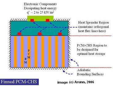
Figure 1. A finned PCM composite heat sink. A heat spreader passes heat from the electronic components into alternating fins of base material (BM) and layers of PCM. Image © Arunn, 2006.
With R. Akhilesh and C. Balaji, we used scale analysis to find, for a given amount of PCM, a critical size for each fin and PCM layer (Akhilesh et al., 2005). A heat sink built from units of this size melts all its PCM exactly when the electronics reach the set point, so none of the stored latent heat is wasted and the operating time is the longest possible. In a worked example, electronics dissipating 62.5 W through a 5 cm by 5 cm heat sink stayed below 90 °C for 453 s with the critical design, against 294.5 s for a poorly sized one. With Atul Nagose, Ankit Somani and Aviral Shrot, we then used a genetic algorithm to optimise the whole geometry, and found that the best heat spreader thickness is 2.5% of the heat sink depth (Nagose et al., 2008).
Designs of this kind are needed to cool the on-board electronics of rockets launched by the Indian Space Research Organisation, which must stay below about 90 °C for the 20 to 30 minutes a payload-carrying rocket takes to reach space. The details, figures and commercial examples are in Phase Change Material Applications.
Carrying heat away inside a heat sink: tree-shaped micro-channels
At the scale of a single device, heat can be carried away by a liquid pumped through micro-channels, fine coolant passages cut into the heat sink. The usual straight, parallel channels have two drawbacks: they need a large pressure to push the coolant through, and they leave the heat sink with an uneven temperature, hotter where the coolant has already warmed up. Many natural flow systems, such as blood vessels, lungs and river basins, branch like trees, and work by Bejan and co-workers showed that when a flow system must balance resistance to flow against resistance to heat transfer, the best design often becomes a tree.
With B. V. K. Reddy and P. V. Ramana, we tested this idea on a realistic electronics heat sink (Reddy et al., 2008). We simulated a silicon disc, 20 mm in radius and 2 mm thick, heated uniformly from below and cooled by water flowing outward from the centre through a network of micro-channels. The network starts as three channels at the centre, and each channel splits into two at every branching level, up to four levels, with channel sizes set by Murray’s law, a branching rule for laminar flow. We solved the flow in the water and the heat conduction in the silicon together, and asked three questions: what coolant flow keeps the disc below 90 °C, how the disc temperature evolves in time after the heat load is switched on, and whether making the channels slightly deeper toward the rim lowers the pumping pressure.
Every tree network needed less coolant than straight radial channels to stay below the set point. More branching lowered the maximum temperature and made the disc temperature more uniform, although each extra level helped less than the one before. Supplied with its own critical flow, each network behaved almost identically as the device warmed up, with maximum temperatures within 2% of each other, which matters for electronics that are switched on and off repeatedly. The more complex networks needed more pumping pressure, but tilting the channels by just 0.1 mm across the radius cut the pressure drop by 45% for the simplest branched network and by 25% for the most complex one (Reddy et al., 2008). More detail is in Tree Networks.
Carrying heat away from a room: a data centre as a bi-disperse porous medium
A data centre can be modelled in full with computational fluid dynamics, resolving every rack and server, but such multi-scale computations are tedious and slow. Another approach treats the whole room as an ordinary porous medium with averaged properties, which loses the structure of the equipment inside.
With B. V. K. Reddy and Pradip Dutta of the Indian Institute of Science, we proposed a middle path: model the data centre as a bi-disperse porous medium (BDPM), a porous medium with two very different pore sizes (Narasimhan et al., 2011). The room, with gaps between the servers, is the macro-porous medium. Each server, a box of electronic components with small gaps for air between them, is a micro-porous block. The same cooling air flows through both. Our model was a channel holding an array of heat-generating porous square blocks separated by gaps, cooled by laminar forced flow of air. Two parameters stand for how the electronics are arranged: the macro-pore volume fraction (how much of the channel is open gap) and the number of blocks (how finely the same electronics are divided and spread out). The background to this porous medium approach is in Bi-disperse Porous Media.
The results give clear design guidance. Raising the open-gap fraction from 0.2 to 0.86 doubled the heat transfer (the Nusselt number rose from about 550 to about 1100) while the pressure drop, and so the fan effort, fell almost eightfold. Below a gap fraction of about 0.5 the benefit faded quickly towards the single-scale porous medium limit. Spreading the electronics over many small, well-distributed blocks transferred more heat than packing them into one large block, because the flow through each cross-section became more uniform and the blocks ran cooler. The gain was large up to 49 blocks and small beyond that, and the pumping power stayed almost unchanged across the whole range (at a Reynolds number of 1500 it rose only from 2.25 to 2.35 in the model’s units). The BDPM approach thus lets a designer tune the layout of a data centre for better cooling without a full multi-scale simulation (Narasimhan et al., 2011).
What ties them together
All three studies ask the same question: how should the paths that carry heat (metal fins, branching channels or open gaps for air) be arranged among the heat sources so that the heat-storing or heat-carrying medium is fully used? In the PCM heat sink, the right fin spacing ensures that every bit of wax melts before the electronics overheat. In the micro-channel heat sink, branching spreads the coolant so that no part of the disc runs much hotter than the rest. In the data centre, the right gaps and distribution ensure that air reaches every server without a large cost in fan power. In both, scale analysis and porous medium thinking give quick design rules where brute-force simulation would be slow.
Related
- Phase Change Material Applications
- Bi-disperse Porous Media
- Tree Networks
- Heat Transfer Enhancement using Porous Media
References
- Narasimhan, A., Reddy, B. V. K. and Dutta, P. (2011), “Thermal Management using the Bi-disperse Porous Medium Approach,” Int. J. of Heat and Mass Transfer, 55(4), 538–546. [DOI 10.1016/j.ijheatmasstransfer.2011.11.006]
- Nagose, A., Somani A., Shrot, A. and Narasimhan, A., (2008), “Genetic Algorithm Based Optimization of PCM Based Heat Sinks and Effect of Heat Sink Parameters on Operational Time”, ASME J. Heat Transfer, 130, 011401, (8 pages). [DOI 10.1115/1.2780182]
- Reddy, B. V. K., Ramana, P. V. and Narasimhan, A., (2008), “Steady and Transient Thermo-hydraulic Performance of Disc with Tree-shaped Micro-channel Networks with and without Radial Inclination”, Int. J. Thermal Sci. 47 (11), 1482-1489. [DOI 10.1016/j.ijthermalsci.2007.11.003]
- Akhilesh, R., Narasimhan, A. and Balaji, C., (2005), “Method to Improve Geometry for Heat Transfer Enhancement in PCM Composite Heat Sinks” Int. J. Heat and Mass Transfer, 48, 2759-2770. [DOI 10.1016/j.ijheatmasstransfer.2005.01.032]