
About this note
A plain-language summary of the 2 publications listed under this topic on Academic Publications (Topic-wise). Full citations are under References.
Why this matters
As electronics shrink, the heat they release from each square centimetre keeps rising; it can now reach 1 MW/m² (100 W/cm²). For the electronics to work without faults, this heat has to be removed quickly enough to keep them below a set point temperature (SPT), usually the junction temperature of the transistors, about 90 to 120 °C.
Portable electronic devices seldom run at peak load for more than a few hours, which makes them good candidates for cooling by a phase change material (PCM), a substance such as paraffin wax or n-eicosane that absorbs a large amount of heat as it melts (its latent heat) while its temperature stays almost constant, and then solidifies again during idle time, ready for reuse. The aim is to keep the electronics below a critical temperature, usually around 90 °C, for as long as possible.
These materials conduct heat very poorly, so heat poured into a block of wax overheats the electronics long before most of the wax melts. The remedy is a composite heat sink, in which fins of a highly conducting base material such as aluminium carry heat into a bath of PCM. The design question is then: for a given amount of PCM, how thick should the fins and the PCM layers between them be, so that all the stored latent heat is put to use?
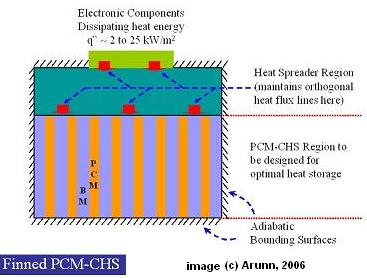
Figure 1. A finned PCM composite heat sink. Electronic components on top dissipate a heat flux of about 2 to 25 kW/m². A heat spreader passes the heat down into alternating fins of base material (BM) and layers of PCM, and the other surfaces are insulated (adiabatic). Image © Arunn, 2006.
What we did
With R. Akhilesh and C. Balaji, we first developed a design procedure based on scale analysis, which estimates how the main terms in the governing equations balance in order of magnitude (Akhilesh et al., 2005). The heat sink was treated as an array of repeating units, each made of half an aluminium fin and the adjacent layer of n-eicosane. For a given heat flux and heat sink height, the analysis gives a critical size for this unit that depends on the fraction of PCM used. We checked the predictions against numerical solutions and proposed a correlation for the critical dimensions.
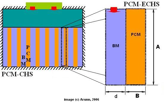
Figure 2. The composite heat sink (left) is built from identical elemental units (right), each a base material fin of width d beside a PCM layer of width B, of height A. Scale analysis gives the critical values d_c and B_c. Image © Arunn, 2006.
With Atul Nagose, Ankit Somani and Aviral Shrot, we then treated the design as an optimisation problem (Nagose et al., 2008). The quantity to maximise was the sink operational time, the time taken for the top of the heat sink to reach the critical electronics temperature. It depends on the amount of PCM, the heat sink depth, the fin size and the thickness of the heat spreader (a layer of base material between the electronics and the fins), the last not previously treated as a design variable. We coupled a genetic algorithm, a search method that mimics natural selection by breeding and mutating candidate designs, with numerical simulations that computed the operational time of each candidate.
What we found
The scaling study showed that arbitrarily sized units can leave some PCM unmelted when the set point is reached, so part of the latent heat storage goes unused. Of the two ways a design can miss, this is the worse one, because the heat sink then performs poorly. The opposite case, where all the PCM melts well before the set point, merely wastes some potential: once molten, the PCM keeps taking in heat only as sensible heat, which raises its temperature, instead of as latent heat. If the fin and PCM layers are made no larger than the critical dimensions, all the PCM melts just as the heat sink reaches the set point, which maximises the energy stored and the time of operation. The proposed correlation predicted the critical dimensions within 10% average deviation. In a worked example, electronics dissipating 62.5 W over a 5 cm by 5 cm heat sink (a heat flux of 25 kW/m²) were to be kept below 90 °C, with half the heat sink volume filled with PCM. The analysis gives critical units with d_c = B_c = 4 mm and calls for 3.2 of them, rounded up to four. With four units the heat sink ran for 453 s, after which it has to be cooled to solidify the PCM before it is used again. Choosing three or two units instead cut this to 410 s or 294.5 s, while nine units gained only 3 s, as the extra heat went into already molten PCM (Akhilesh et al., 2005).
The genetic algorithm study found that, for all the heat sink depths considered, the best heat spreader thickness was 2.5% of the heat sink depth. From the optimised designs we derived correlations linking the operational time to the PCM fraction, depth and spreader thickness; they reproduce the simulations within 4.6% for operational time and 0.32% for PCM fraction. They let a designer find the longest operating time for a given space, or the most compact heat sink for a required time (Nagose et al., 2008).
In practice
Composite heat sinks of this kind are not far-fetched. Energy Science Laboratories Inc. (ESLI) made paraffin-based PCM heat sinks that use light, brush-like metal fibres pervading the PCM in place of the simple parallel fins of Figure 1. They were designed to hold temperatures of 5 to 61 °C, and were flight-tested on the Space Shuttle (STS-95) in the CRYOTSU experiment module.
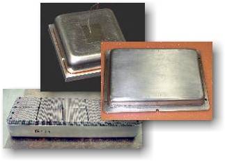
Figure 3. PCM composite heat sinks made by ESLI, with metal fibres as the conducting base material. Image: ESLI.
A design not unlike that of Figures 1 and 2 is needed to cool the on-board electronics of rockets launched by the Indian Space Research Organisation (ISRO). There the heat sink must absorb as much energy as possible while keeping the electronics below about 90 °C for 20 to 30 minutes, the flight time of a payload-carrying rocket one way into space. NASA has used a variant with carbon fibres as the base material to cool on-board batteries in space vehicles.
Related
- Thermal Management of Electronics and Data Centres, which places this work alongside our data-centre cooling research
- Optimization and Genetic Algorithms
- Stefan and the Polar Ice Caps, on the classical melting and freezing problem used to benchmark such simulations
- Tree Networks, another approach to cooling electronics
References
- Nagose, A., Somani A., Shrot, A. and Narasimhan, A., (2008), “Genetic Algorithm Based Optimization of PCM Based Heat Sinks and Effect of Heat Sink Parameters on Operational Time”, ASME J. Heat Transfer, 130, 011401, (8 pages). [DOI 10.1115/1.2780182]
- Akhilesh, R., Narasimhan, A. and Balaji, C., (2005), “Method to Improve Geometry for Heat Transfer Enhancement in PCM Composite Heat Sinks” Int. J. Heat and Mass Transfer, 48, 2759-2770. [DOI 10.1016/j.ijheatmasstransfer.2005.01.032]